SUBSEA CABLE INSTALLATION
We provide our customers with an experienced team of engineers to plan and design solutions, effectively manage entire projects together with clients, and execute scopes of work supported by our highly capable assets which have an extensive track record in offshore installation.
• Multipurpose subsea installation vessels
• Plough and ROV burial solutions for various types of cables providing protection from fishing and other third-party risks.
• Project support at all stages, from planning to final survey and as-built reports
• Engineering, Project Management, Ploughing and Trenching delivery
• Marine surveys, Permitting, Offshore liaison and Charting/system documentation management services.
Project Management
We serve in deep and shallow waters our marine engineering partner capable of providing a complete end-to-end solution that supports the whole life of a subsea project from planning, installation, protection, and repair.
Project Engineering
Well qualified, highly experienced engineers have the knowledge and capability to deliver complex end-to-end engineering support, on time and to specification every time. Our project engineers can either be integrated within our customer’s own engineering department at their premises or managed “in-house” location.
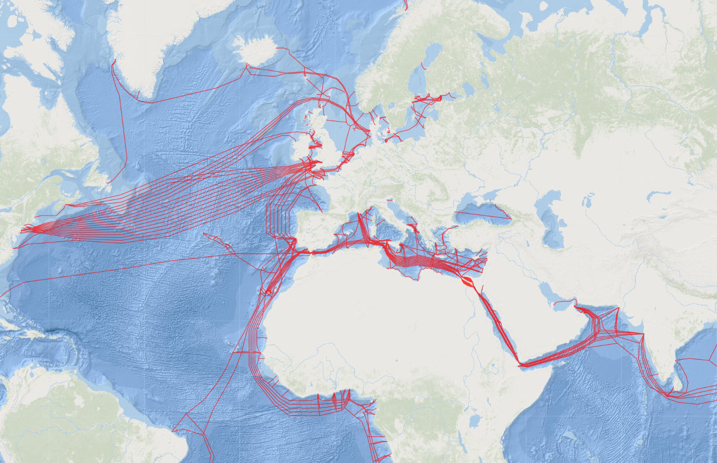
Cable Route Planning
With a group of experts and knowledgeable team we deliver a comprehensive Cable Route Planning portfolio of services for the telecoms industry.
Our services cover:
|
2. Desktop Study 3. Route Survey 4. Route Engineering 5. Cable Fault Analysis 6. Cable Protection Assessment |
|
Permits
We need permits and on advice to navigate and complete the complex and varying multi-national permit requirements for projects covering worldwide ensuring that project is properly licensed and authorised.
Offshore Liaisons
Offshore Liaison is key to maintaining strong relationships with all stakeholders of the sea. Promoting close working relationships ensures continued business success for all parties and achieves a collaborative approach.
Design
A Fibre Optic Cable consists of an inner optical core encased within a high tensile steel strength member, clad within a copper power conductor. The package is then insulated with polyethylene. The package is the basic deep-water cable and is usually 17 – 21mm diameter.
The optical (light) signal is carried on pure glass fibre cased within the core. The light is guided by internal reflection within the glass fibre. Each fibre, there may be many in the tube.
Because the light signal loses strength over longer route, repeaters are required at regular intervals to restore it. Repeaters are the amplifying technology, which requires short lengths of erbium-doped optical fibre to be spliced into the cable system. These are then energized by lasers, thus boosting the incoming light signal. Repeaters need to be spaced every 50 to 80 kilometres apart and since each repeater requires electrical power to operate it, therefore long length submarine cables are powered, and the voltages carried may be very high. Damage to, or loss of a repeater can result in a very expensive repair or replacement, as well as breakdown in commercial business communications.
Shorter submarine cables do not need repeaters and have amplifiers at either end. It is possible to have a single span of around 240km without the need for a repeater.
Cable systems may also have devices called Branching Units inserted into them. The Branching Unit looks like a ‘Y’ shaped cable connector and are very large. The branching unit can be used to split the cable path to enable the cable to be routed to two or more different locations thus allowing diversity of connection for the cable system. More than one Branching Unit can be used in a cable system and indeed, many cable systems use multiple Branching Units to allow multiple connections.
In water less than 2,000 meters deep, additional protection is added against environmental, fishing and anchor damage in the form of external steel wire armour clad within a polypropylene serving. There may be one or more layers of armour applied to the cable.
The heaviest form of armoured cable may have more than 70 tonnes breaking strength. While the cable may only break or part at high tensions, damage to the optical path or to the electrical insulation (the polyethylene) can occur at much lower tensions such as when fishing gear may become engaged with the cable. This is because the cable becomes bent to a radius less than its minimum safe limits (usually 1.5 metres radius/3 metre diameter). Armoured cables vary in size depending on whether one or more armour layers are used but may be up to 50mm diameter. Breaking strains vary from 20 – 70 or more tonnes.
Selection of provisional route
Once the requirement for a cable system has been identified and funds raised to build it, the first thing which happens is that a cable manufacturer and installer is contracted by the cable system parties.
A desk top study is then commissioned which identifies a route and the risks to that route. Items for consideration would be: -
• Landing Points, Territorial waters, Contiguous Zones (CZ) and Exclusive Economic Zones (EEZ) i.e., the Maritime Boundaries.
• Cable selection.
• Branching Unit deployments.
• Geopolitics – Contested Areas.
• Burial requirements.
• Whether the cable landings can be made directly or must be pre-laid.
• Permitting & Fisherman Negotiations; and
• Natural and manmade obstacles/hazards such as weather conditions prevailing, currents, seabed conditions, Mineral and/or Oil & Gas exploration, Pipelines, other submarine cables, areas of environmental concern, conservation area etc.
Obtaining permission from the relevant authorities
When the route has been selected and designed, then the initiation of acquisition of permits for the cable system is undertaken. This will involve engagement with Government Administrations, other seabed users and stakeholders i.e., fisheries, cable owners, pipeline owners, etc.
Full survey of route and its final selection
The purpose of the route survey is to identify a safe route for the cable. Even though the Desktop Study has identified the potential route, the Route Survey will confirm the assumptions made. The Route Survey comprises:
Collection of Bathymetry, geotechnical, sub-bottom and side scan data to support route engineering, cable selection, installation, and burial.
The data is made available for review real-time and thus a final selection of the route can be made. Final route selection will consider identifying the safest and most economical route, will optimize cable selection and route length. Avoidance of any hazards identified during the survey process can be made and cable types to be used will be confirmed. An assessment of seabed conditions is also made at this point for the buried sections of the cable. Obtaining permission from the relevant authorities
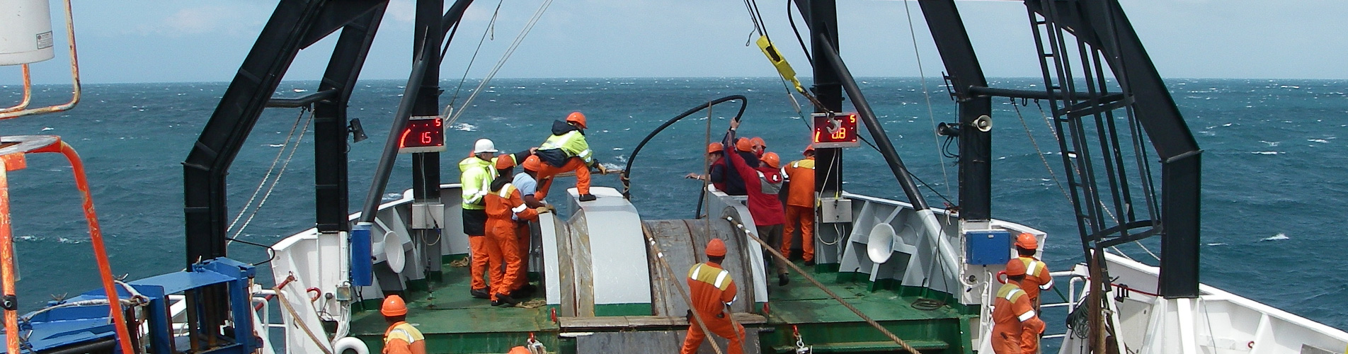
Cable laying Operations
Once the route survey is complete and the cable system design is finalised, manufacture of the cable is undertaken. The cable manufacture loads in the cable ship for deployment.
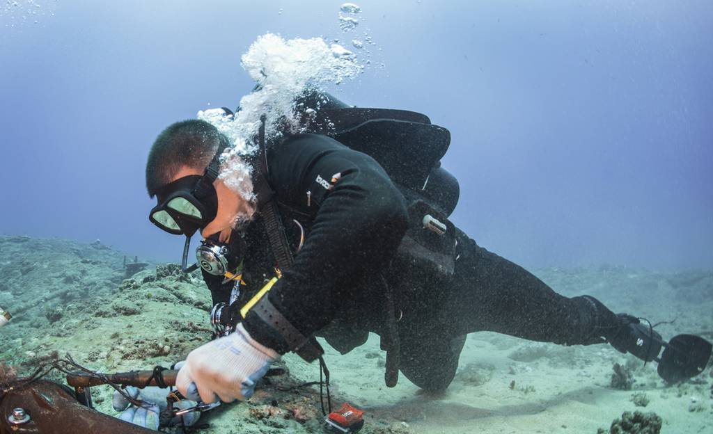
At the shore approaches where the cable is landed (the shore end), burial is carried out by divers in the shallow water. If the water is too shallow for the main lay vessel to approach safely, a smaller shallow drafted vessel may be lay used to lay the shore end.
The main lay cable ship is used to lay the rest of the cable system. In water depths where there are risks due to fishing and other man-made activities such as anchoring etc., the cable is generally buried to a target depth of approximately 1 metre.
The cable is laid to conform to the contours of the seabed to avoid cable lying in suspension. During the cable laying process, the cable is being constantly tested to ensure that no damage has occurred to it.
At the end of the cable lay, a final splice is made to join the cable ends together to make a connection between the cable stations. Final tests are then made to ensure the cable is working correctly.
Notification of cable position to other marine users
Following the cable laying operations, the cable positions will be notified to various administrations such as Hydrographic Offices, the Regulatory Administrations and other seabed users such as fisheries.
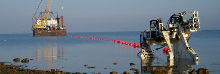
Cable Burial
At the planning and installation phase of a submarine cable project one of the most effective methods of protecting a submarine cable from damage caused by external aggression is to bury the cable, usually with a sea plough.
This burial is very much dependent on suitable seabed conditions and sediments along the cable route, it should be noted that in areas where seabed conditions do not allow for cable burial other methods of cable protection may be employed, such as additional cable armouring, articulated ducting, or rock placement.
Due to the nature of some areas of seabed where mobile sediments are found, cables that were buried at the time of installation may become exposed over time, therefore it should not be assumed that all submarine cables are completely protected by burial as they may become exposed and on the surface.
In water depths up to approximately 2,000 metres, the cables may be buried in a narrow (<1 m wide) trench cut by water jet or plough. The usual and most efficient burial method is by use of a subsea cable plough which is towed on the seabed behind the cable ship. The cable passes through the plough and is buried into the seabed. The plough lifts a wedge of sediment so that the cable can be inserted below, thus minimising seabed disturbance to a very narrow corridor. Burial speed depends on cable type and seabed conditions but for an armoured cable, the burial speed is typically 0.2 km/hr.
If it is planned to plough bury the cable, following the survey and usually a few weeks before the main laying and ploughing operations take place, a seabed clearance operation called a Pre-Lay Grapnel Run (PLGR) operation is carried out. This is to remove items of debris such as abandoned fishing nets, wires, hawsers etc. Removal of any debris ensures a clear route for the plough to negotiate so that burial can be maximised.
There are also old submarine cable systems remaining on the seabed and these too are cleared from the burial route for a short distance each side. The cable ends are weighted with clump anchors so that the cable cannot be snagged by other seabed users such as fishermen.
Following plough burial, a post lay burial and inspection is normally carried out in areas where the plough could not bury, such as at cable and pipeline crossings, locations where the plough may have been recovered for repairs etc. This burial is carried out by a Remotely Controlled Vehicle (ROV), which buries the cable to the same target depth as the main lay plough but by use of water jetting. This operation also minimises seabed disturbance. At pipeline crossings, due to pipelines often being situated proud of the seabed, further protection to the cable and pipeline is normally made by means of a post lay rock placement operation. The rock placement is carried out under highly controlled conditions to place a layer of rock over the cable at the pipeline crossing location, to add a final protection layer. The rock berm is designed to minimise risk to fishing gear by specific selection of rock size and berm side slopes.
Submarine cables have been laid on the seabed since long. In most cases, recently installed cables are buried beneath the seabed to a target depth of 1 metre, unfortunately there remains a percentage of cable unburied. Cables can be scoured out by tides and currents or moved by anchors and fishing gear. Therefore, cables that were considered safe from subsea activities at the time of installation may become unburied.